Remember that a data hazard occurs when an instruction waits for the result of a previous instruction.
In the following example:
        add a0, t0, t1         ; a0  ←  t0 + t1
        sub a1, a0, t2         ; a1  ←  a0 - t2
the add instruction stores the result into register a0 when it reaches the
Writeback stage at clock cycle 5,
but the sub instruction wants to read a0 when it reaches the stage Decode
in clock cycle 3.
Of course, at cycle 3, the result of the first instruction has not been written
into the register file yet.
Instead of waiting two cycle for the value to be available, we could instead
create a shortcut, a way for the second instruction to get the value of a0
directly out of a subsequent stage of the pipeline. In other words, a bypass.
In practice, it's not just one bypass that we need but several of them!
The forwarding unit
The Execute stage needs to know the correct value for both rs1 and rs2
and each of them can come from three different sources:
- The register file. That's the canonical source for the value, no bypass is used.
- The output of the previous instruction. This means the value is present in
the
EX/MEMpipeline register, which is equivalent to say that it comes from the Memory stage. - The output of the instruction before that. In this case, the value is in the
MEM/WBpipeline register, or in the Writeback stage.
Any instruction before that will have had the time to go through the Writeback stage.
Here is how we determine the correct source for the value of rs1:
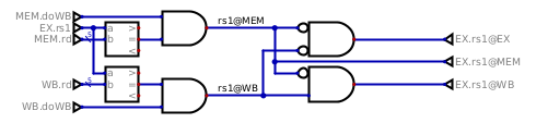
The forwarding unit is always active, it does not care whether the register is actually needed by the ALU operation or not.
The logic is not very complex. First, a comparison is made between the the
source register number and the destination register number of the previous two
instructions (the one in MEM and the one in WB). Then it is also checked
that these previous two instructions do actually want to write a value back.
A store instruction, for instance, does not write anything back in the
register file, so cannot be the source of a bypass.
After these two tests, we know if rs1 is present in MEM or in WB (or
both), and it is only a question of priority to know where we want to take it
from. Highest priority is MEM, then if not present there, try to take it
from WB, and otherwise default back to what was fetched from the register
file.
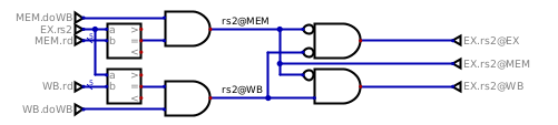
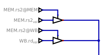
The logic is exactly the same for rs2:
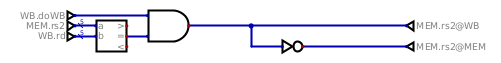
There is another place where a bypass is required, it's in the Memory stage.
When a load into a register is immediately followed by a store of the
same register, this value must be forwarded as well.
The bypasses
All right, we have all those signals coming out of the forwarding unit, but what do we do with them?
We wire the bypasses, of course!
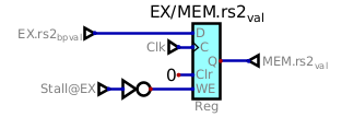
The first bypasses are the ones in the EX stage, and they look like this:
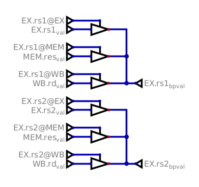
The selection signals will enable only one buffer for each of rs1 and rs2,
so that the correct value can be sent to the ALU or further down the pipeline.
In the Mem stage, it's the same principle, only simpler because there is
only one register and two sources:
The stall logic unit
There's one situation where we cannot rely just on a bypass, though, it's the
use of a register by the ALU in an instruction directly following a load.
The second instruction needs to wait for the value to be loaded from memory,
and for that it needs to be stalled.
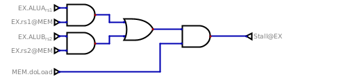
We stall if the ALU wants, as one of its input, the content of a register that
would come from the previous instruction, and that previous instruction is a
load. All the other cases are covered by the bypasses we just implemented
above!
The stall mechanism
Let's keep things simple for now and consider that a memory access can always
be done in one cycle. As a consequence, the instruction present in the EX
stage cannot advance and must stay in there, while the load instruction in
MEM stage moves to the WB stage. That leaves a bubble between them.
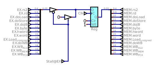
If the instruction in EX cannot advance, neither can thoses in the previous stages Decode and Fetch.
On all the pipeline registers between EX and Mem, a stall signal
will prevent a new value to be clocked in by disabling the Write Enable input:
The same signal is applied to the other pipeline registers in ID/EX and
IF/ID, as well as to the fetch unit so that the PC does not get incremented.
There is just one pipeline register that we need to treat differently: the
register that conveys the actual instruction's actions from EX to
MEM, that one must be cleared to become a nop, our bubble.
This concludes the part on how the data hazards will be handled in Astorisc. Stay tuned for the next part where we'll tackle the control hazards induced by the jumps and branch operations.