The HP 715/80 workstation has an unusual port for input devices that requires the use of an adapter box: the HP HIL A4022-62005. This module sells at an insane price, even without its cable, so the only reasonable thing to do was to make one myself.
At the back of the station is a socket for a modular connector, much like a
network plug, but with 10 pins instead of 8.
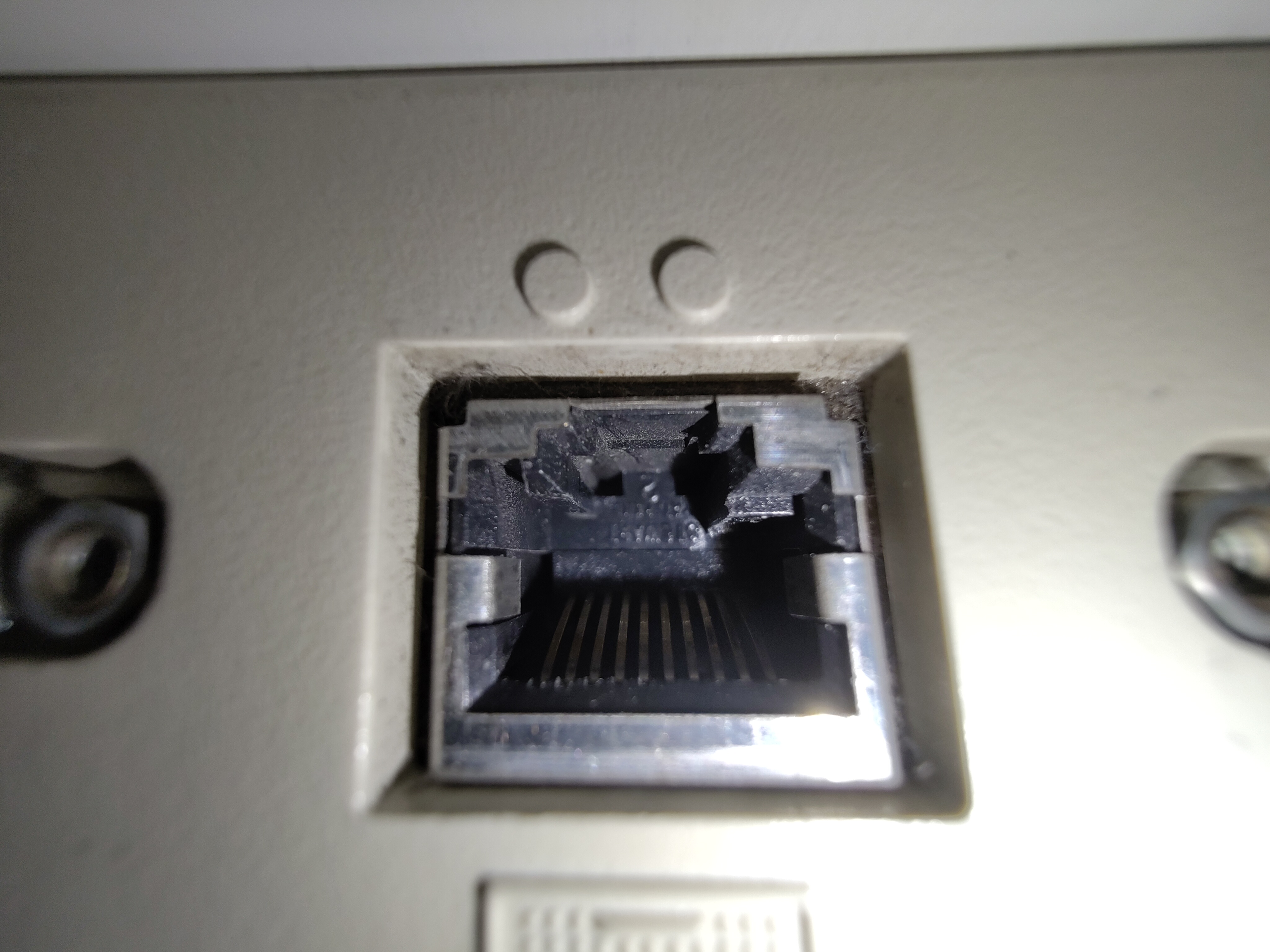
If you look closely, you can see that it is also keyed on the left, certainly to prevent anyone plugging a network cable in there.
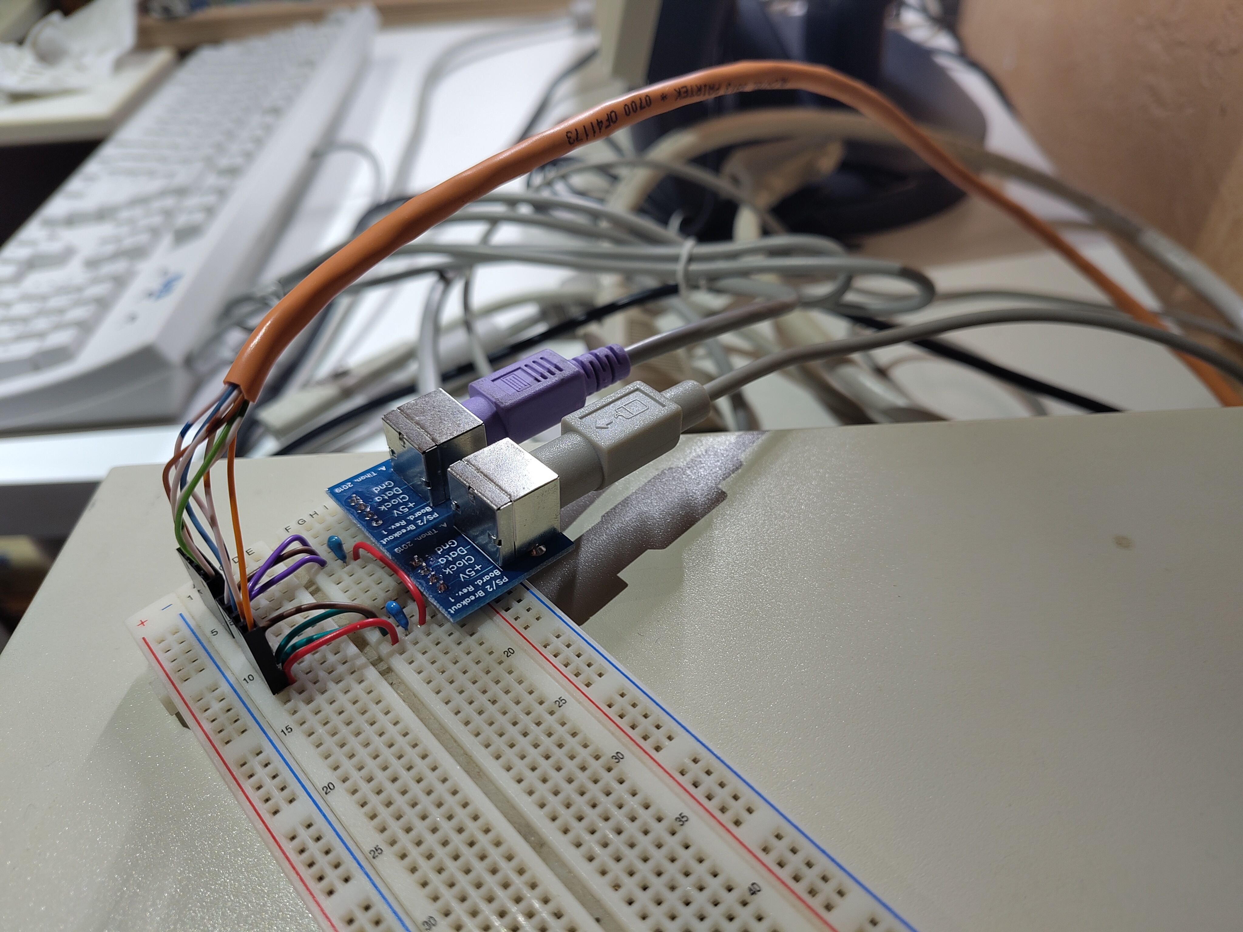
Thanks to nater1217 on the VCFed forum, the pinout is known! and has also been submitted to pinouts.ru.
Many thanks also to Anders Gustafsson for sharing his Adventures with HP HIL, especially for the part numbers of compatible connectors.
The good news is that, in addition to HP HIL, PS/2 keyboard and PS/2 mouse signals are both directly available on this connector, and the adapter box doesn't need any logic. This was confirmed with a quick prototype on breadboard:
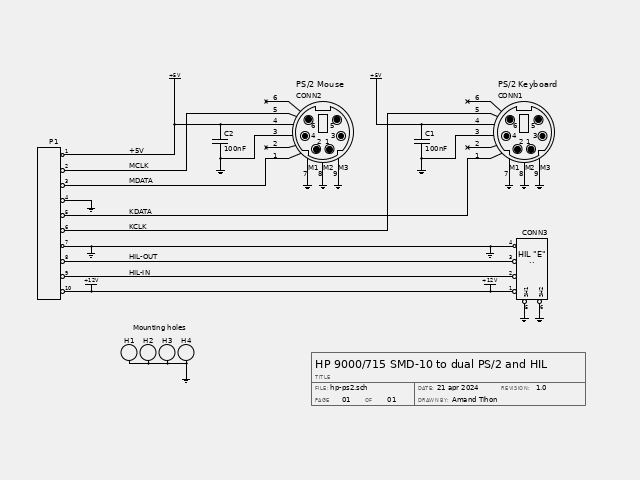
Now I know it's working, but I'd rather have all that in a nice box, so I designed a PCB that would fit in a small 10cm by 6cm box.
The schematic is extremely simple:
And the PCB isn't very complex either:
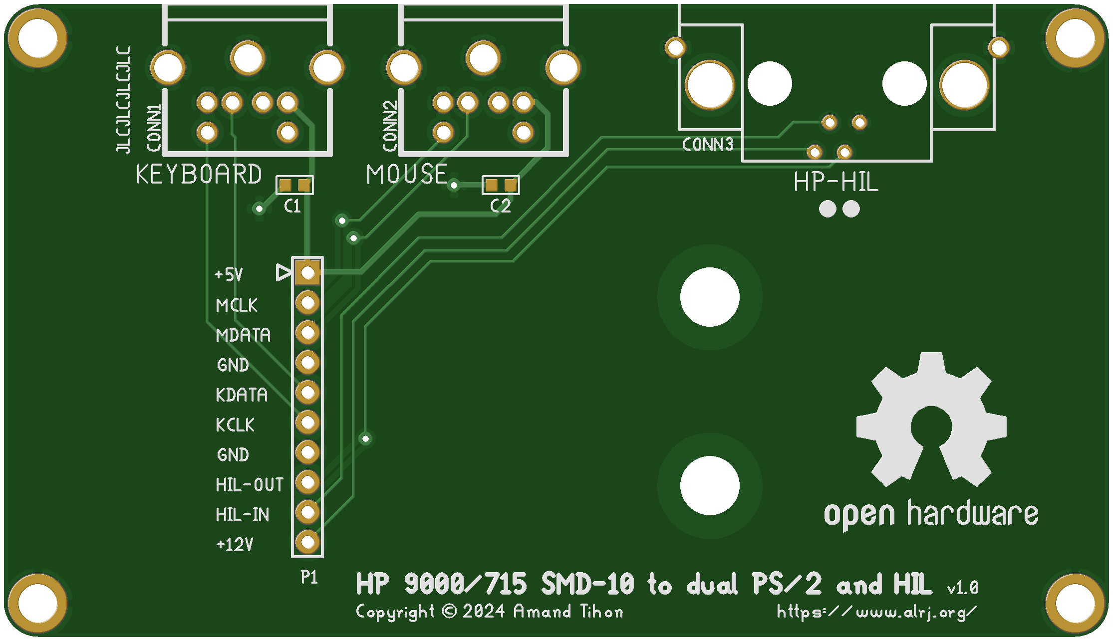
Note that I have included the HIL connector, but I give absolutely no guarantee that it will work, this is entirely untested and the order of the pins could very well be swapped! Use it at your own risk.
The gerber files were then sent to JLCPCB and the printed circuit boards arrived after
a few days.
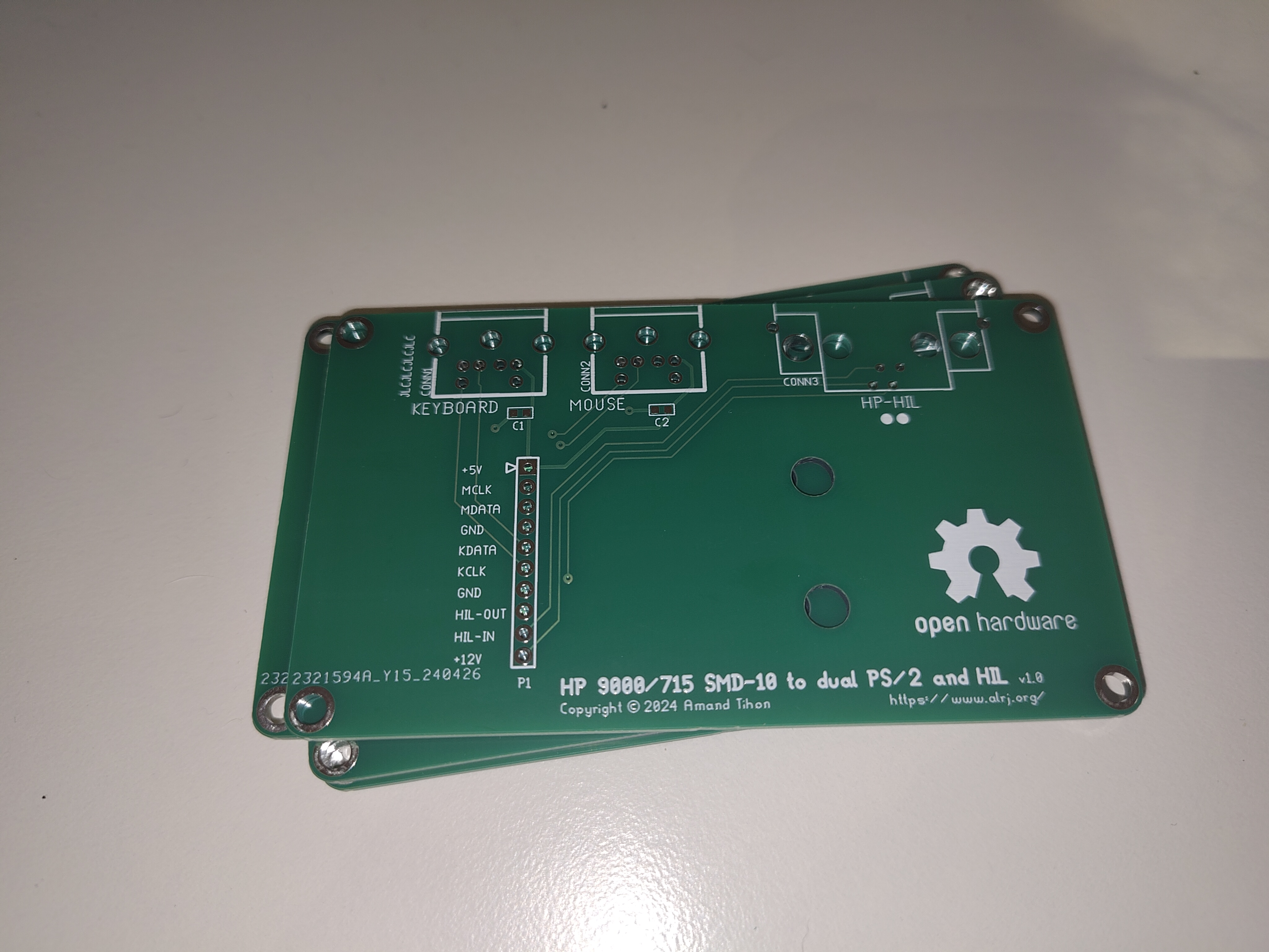
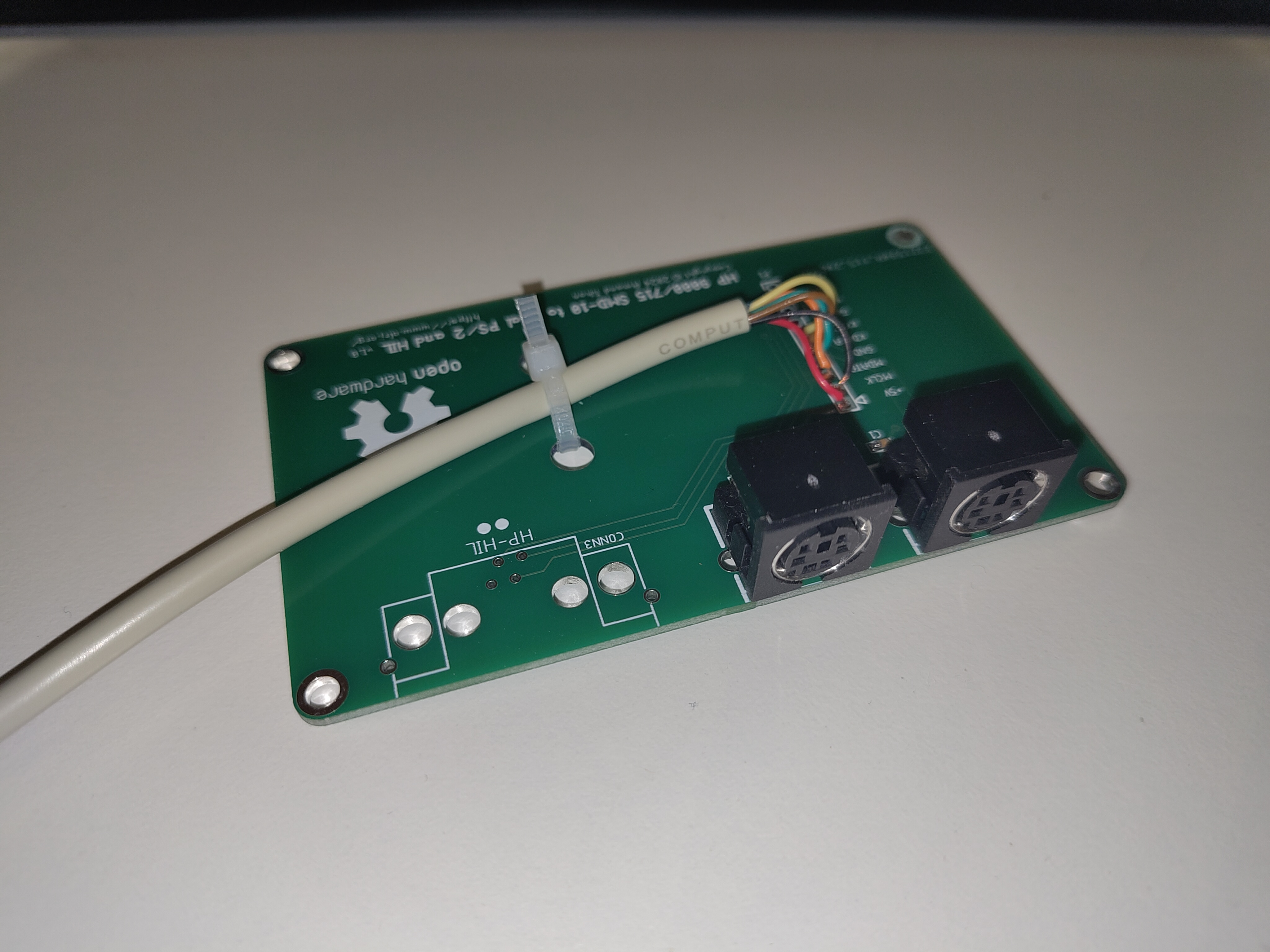
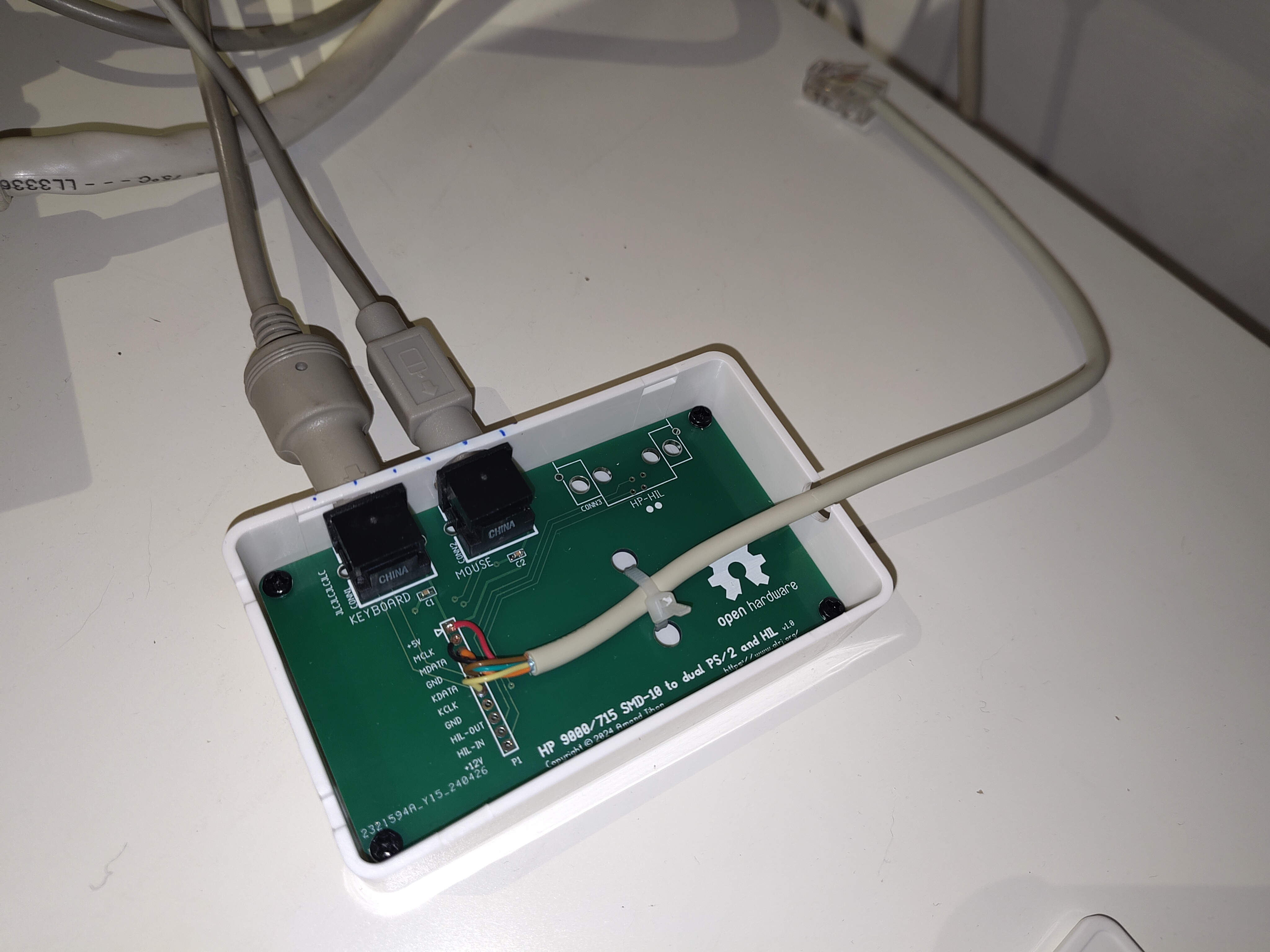
Assembly was straightforward. In hindsight, I wish I'd used a right angle pin header instead of soldering the wires directly to the board, but I don't have any in stock. Well, I have ordered some, and I can always change it later. (The box is too small for vertical pin header).
The cable I used comes from a PS/2 extension cord and has only 6 conductors (plus shielding, that I didn't use); that's just enough to get the two PS/2 connections working!
The two holes are used to firmly secure the cable with a zip-tie.
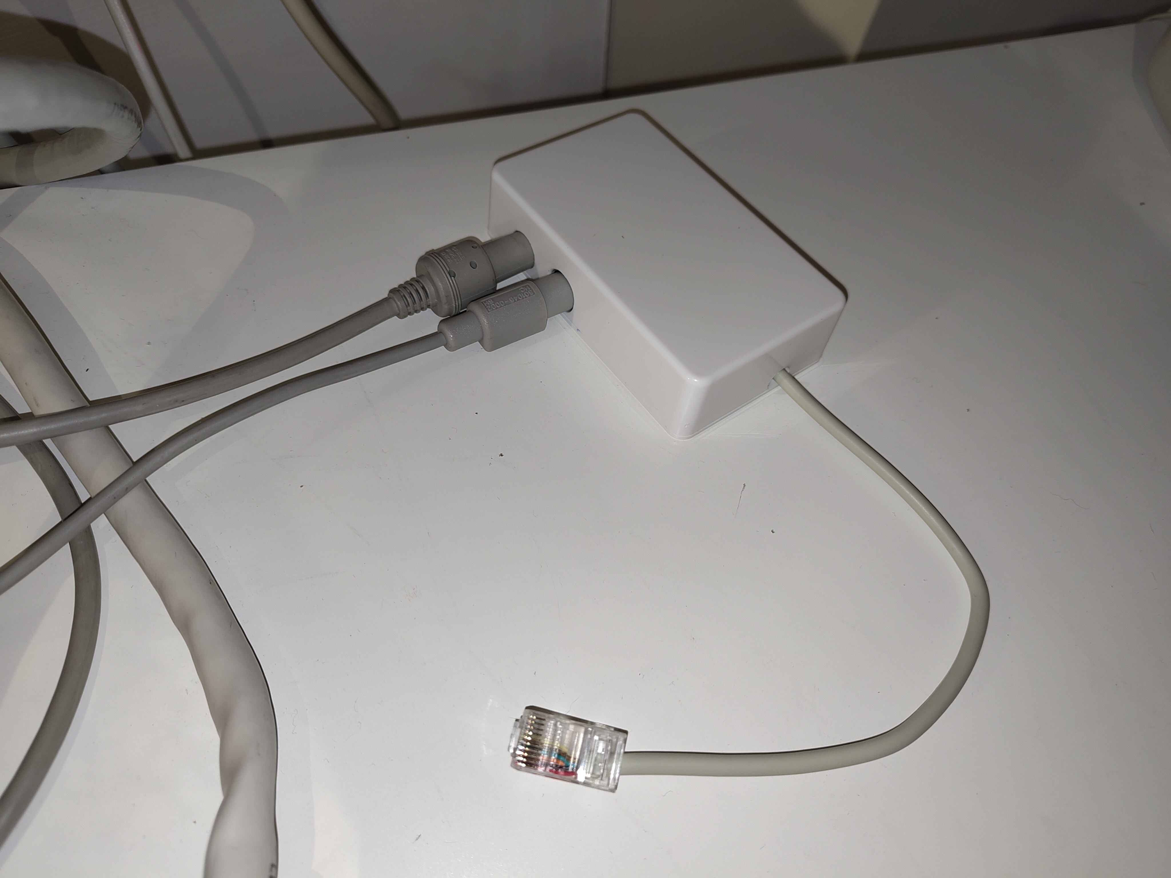
Enjoy a few more pictures of the circuit assembled and put in its box.
The schematic was made with Lepton EDA and the PCB with pcb-rnd.
You can download an archive of the sources of the project or go to the project page on framagit.